Creating an Operation Plan Lifecycle
An Operation Plan Lifecycle specifies the workflow of the Actions in an Operation Plan Counter. When the Counter is activated, Actions are executed, generating the respective Tasks.
The diagram below illustrates the working of an Operation Plan Lifecycle.
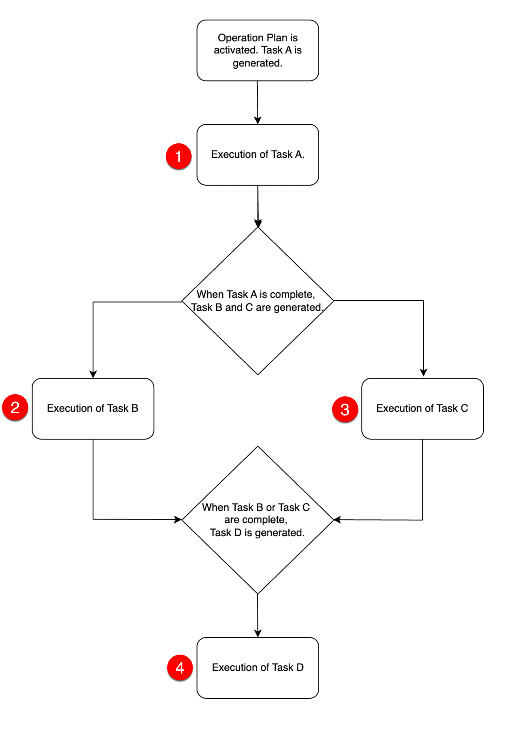 |
You can build a Custom Lifecycle of type OP Plan.
To create an Operation Plan Lifecycle:
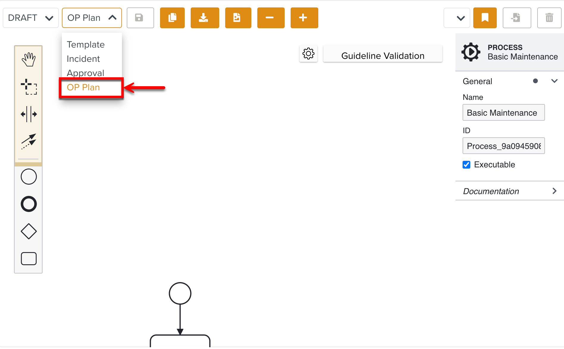
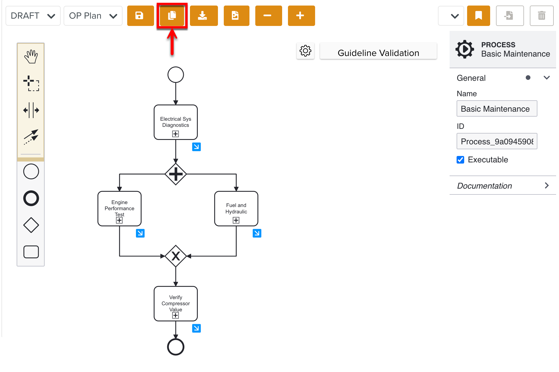
Select the type OP Plan from the dropdown list as shown below.
Drag the required elements from the UI panel to build a Custom Lifecycle.
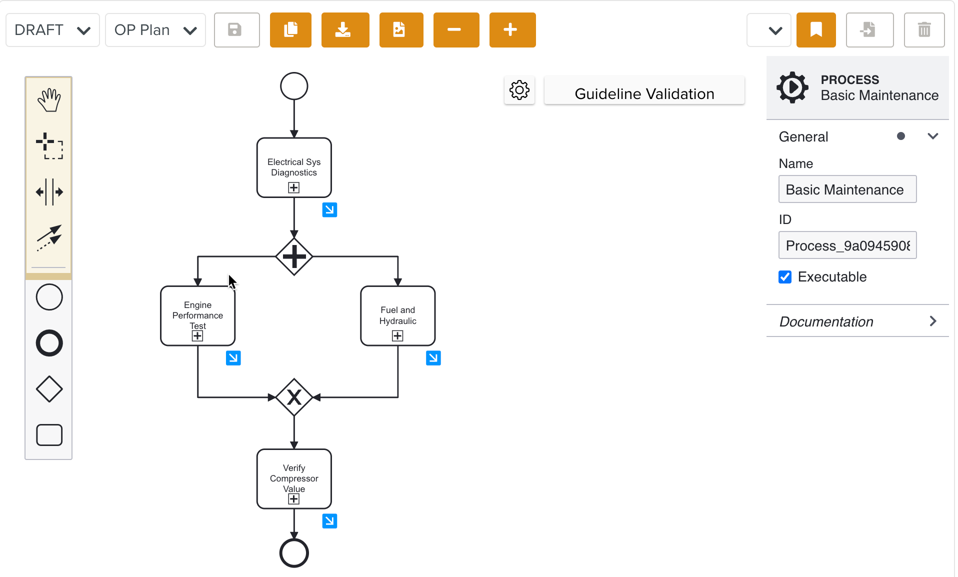
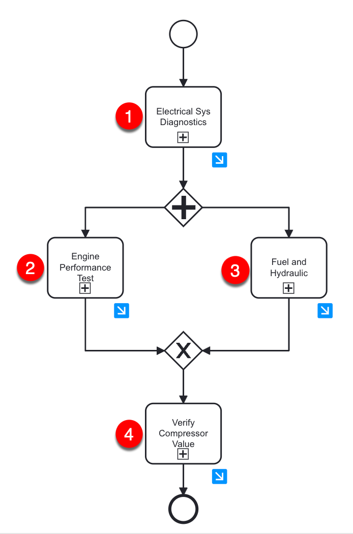
In the below example, the different stages of the Basic Maintenance Lifecycle are highlighted. There are four Sub-Process Task elements as shown below.
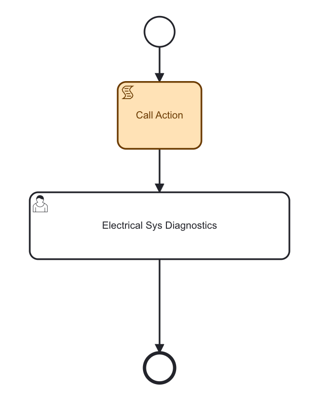
Each Task contains a Sub-Process. The Sub-process workflow includes a Script Task and a User Task as shown below.
In the Script Task, the JavaScript is added to the Script expression field.
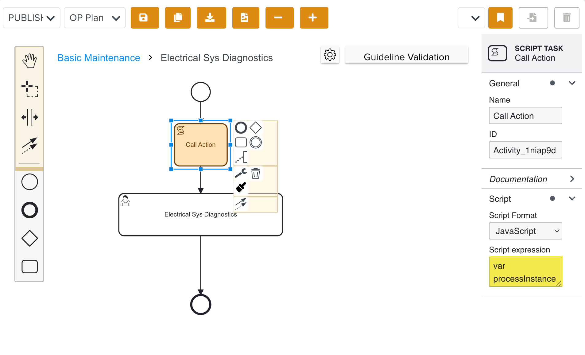
In this example, the below script is added to execute the Operation Plan Action and generate a Task.
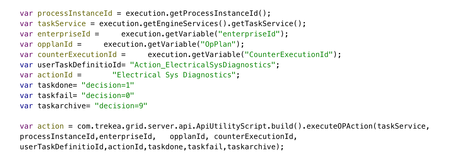
The values of the highlighted variables, userTaskDefinitioId and actionId are modified for each Action.
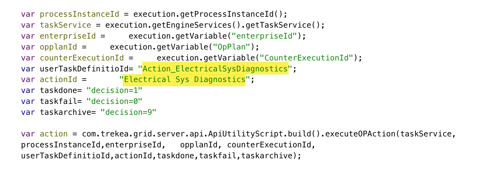
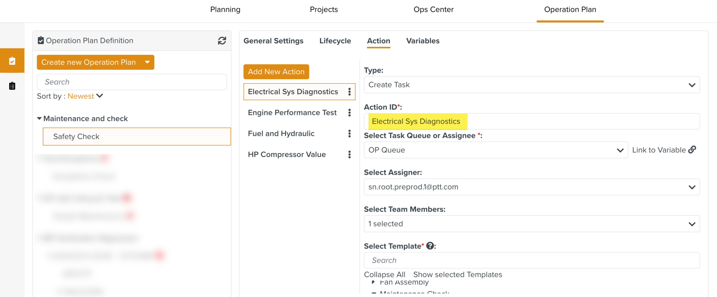
The Action ID of the respective Action in an Operation Plan Counter is used in the script as shown below.

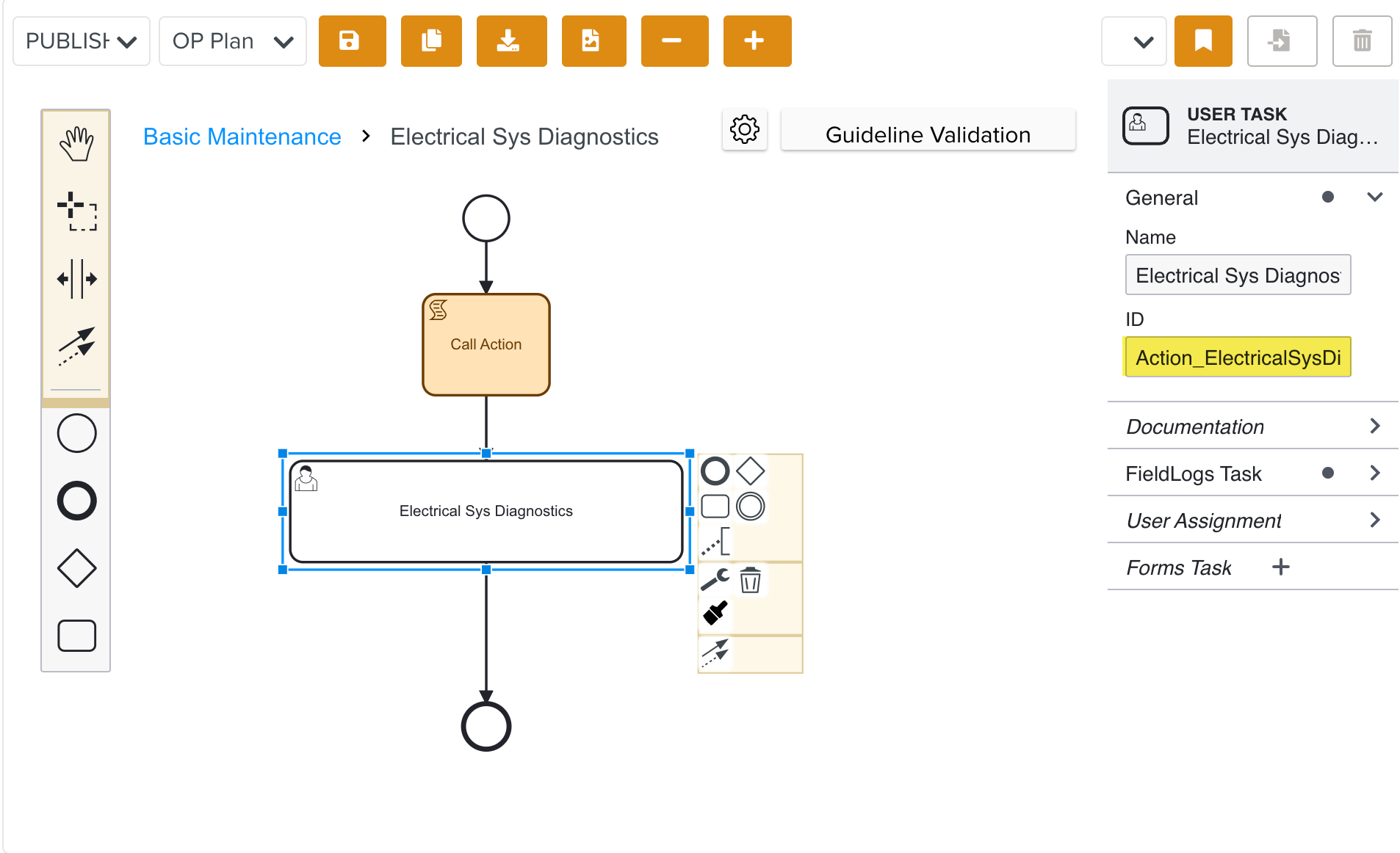
Similarly, the User Task ID is used in the script as shown below.

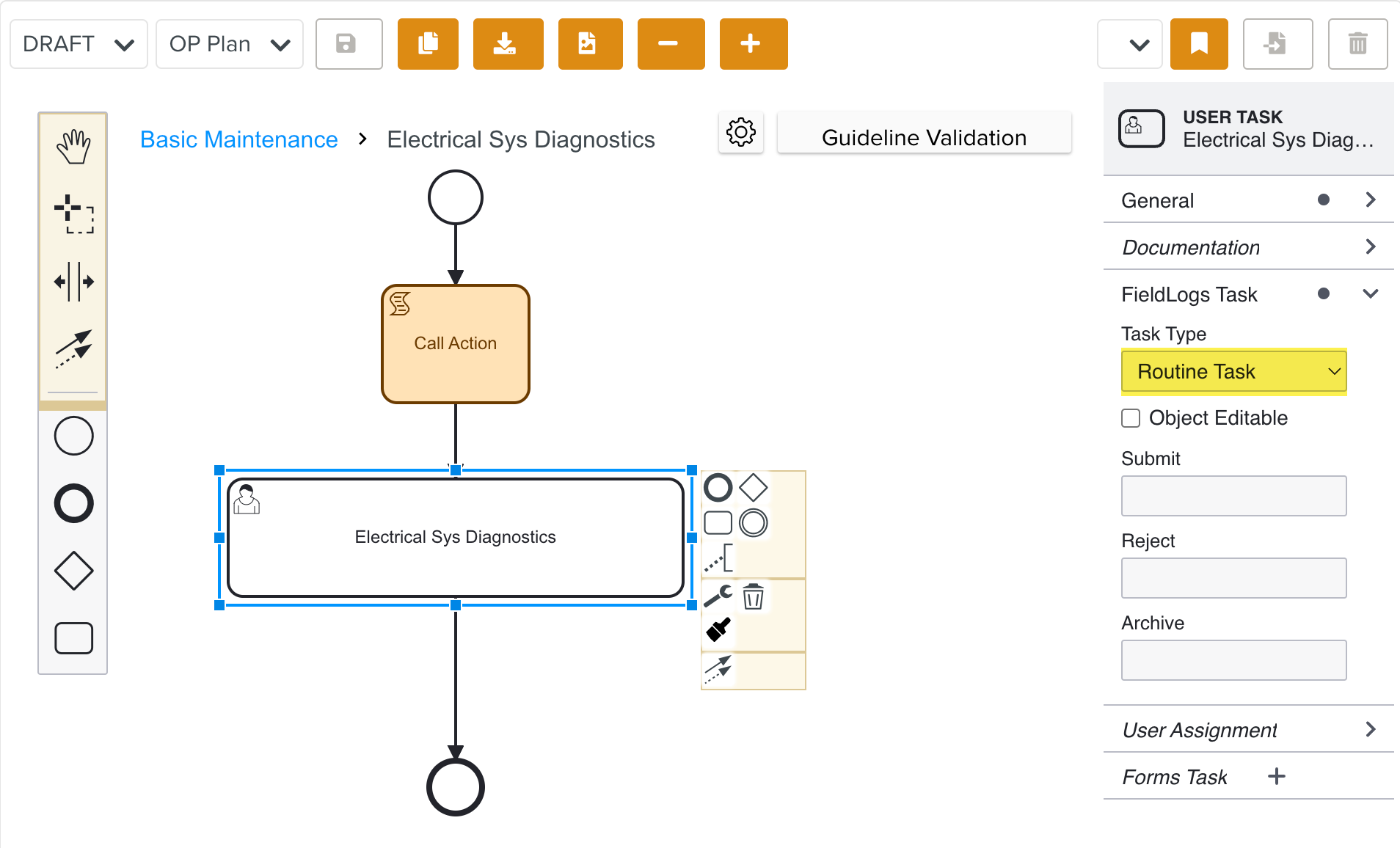
The FieldLogs Task property of the User Task is set to Routine Task.
Each stage of the Lifecycle is associated with an Action. When an Action is triggered with the help of the script added, the respective Task is generated. On the completion of each Task, different Tasks can be generated based on the definition of the Lifecycle.
A Parallel Gateway and an Exclusive Gateway are used in the Lifecycle to determine the execution pathways.
Conditions can also be set to trigger different Actions.
The result of the Task execution is mapped to decision actions that are controlled by a Lifecycle variable named 'decision' with values as follows:
Task Done = 1
Task Fail = 0
Task Archive = 9
These decision values enable conditional branching within the workflow diagram. Depending on the action performed, the workflow uses the 'decision' variable to route the process to the appropriate next step.
Click Save.
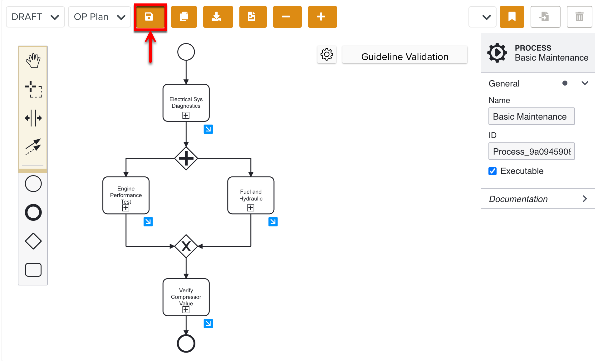
You can save the workflow diagram at any point during creation, which will save it as a Draft. This allows you to pause and resume work without losing progress.
When the Lifecycle design is complete, you can Publish it.
Click Publish.
You have created an OP Plan Lifecycle that can generate Operation Plan Tasks.